WSJT for Meteorscatter
Weak Signal Communications by K1JT, an introduction.
Catharinus van Tuijl, PE1AHX
![]()
![]()
![]()
This article is an adapted and expanded version of the articles written by Juho “Jussi” Kukkola OH6ZZ, member of the OH8K gang (http://www.oh8k.org) which appeared in 2004 in the Finnish magazine Radioamatööri.
Have you ever wondered where the increase in 144MHz DX is coming from? The past few years show a great increase in spotted DX in the DX-cluster (http://www.dxsummit.fi/) which shows that distances of some 2000km or more have been crossed. There is also a large increase in EME activity in the 144MHz band with often unknown and/or small stations. Besides the – of course – continuous technological advances these events are especially the result of a relatively new software program: WSJT ( http://physics.princeton.edu/pulsar/K1JT/ ). Even though the program can be used for a variety of propagation sorts – also on 6m and HF, this article will be limited to using it for meteorscatter in the 2m band. There will only be a summary introduction into the how and what of meteorscatter. There are many sources of information available on the internet.
Introduction.
The past few years Joe Taylor, an astronomer and in 1993 Physics Nobel prizewinner (http://almaz.com/nobel/physics/1993b.html) has been developing and continuously improving a software program for meteorscatter, 6m ionoscatter and EME. The program is also used for weak signal communications on other bands, including HF. This software – WSJT – contains the following modulation types: JT65 – the successor to JT44 in older versions of the software – which is especially being used for very difficult weak signal communications such as EME, long distance tropo or in the HF bands. JT6M has been developed for meteorscatter and ionoscatter in the 6m band with it’s own special characteristics. Finally there is FSK441 for – especially – meteorscatter in the 2m band. There are three versions of FSK441: FSK441A, B and C. The difference between the versions is the build-in error correction in the B and C versions. The consequence of this error correction is however that the actual data speed decreases substantially. This data speed (8820 characters/minute for FSK441A) drops by approximately 57 percent (to 3780 characters/minute) when using FSK441C. Data speed is especially important on the higher VHF and lower UHF bands because of the usually very short reflections. This is the main reason why FSK441A is the default mode in IARU Region-1. This paper will deal with FSK441A and meteorscatter in the 2m band. It is based on version 4.9.8 of the program. I strongly suggest that you read the WSJT version 3 user guide (the older user guide) http://www.pe2pe.eu/wsjt_manuals.htm in addition to this paper.
Meteorscatter.
We all know the phenomenon which is popularly called “falling stars”. This does certainly not describe stars but space dust which burns at about 80 to 110km altitude into the E-layer of the earths atmosphere. The word “dust” can be taken quite literally here as these particles are usually smaller than a grain of sand. Besides the visible effects – bright stripes in the evening sky – these burns also cause ionization at these altitudes. These areas of ionization can be viewed as irregular shaped mirrors to our radio signals. The reflections occur at different and unpredictable places. The numbers peak at various times during the year, with maxima during meteor showers such as the Perseids, Geminids, etc. (http://www.amsmeteors.org).
Current meteor activity can be seen
on various internet sites with real time sounding information such as
http://alwin.rocketrange.no/SKiYMET/flux.htm .
A footnote is
needed here: these soundings often take place at the lower VHF-bands such as 35
or 52MHz. The number of reflections in the 2 meter band is substantially less
when measured with similar power and antenna’s. However, because our amateur
equipment is often very sensitive and we get extra gain from our directional
antenna’s we often detect meteors which do not show up in the counts. Sounding
information is therefore only indicative and not authorative.
When using meteor reflections for radio purposes we differentiate between bursts and pings. A burst is long enough to contain useful information, a ping is too short for that. By using this real life definition to today’s operations one can conclude that there are almost no more pings because even a duration of about 20ms (2/100th of 1 second) contains useful information – in FSK441A 3 characters. Because of the height at which reflections occur the usable distance for QSO’s is some 700-2300 kilometers where the shortest as well as the longest distances are most difficult. The optimal distance appears to be around 1250 kilometers. Larger distances are possible (4 QSO’s over 3000 kilometers are known) but only a the result of double reflections (double hop MS) or Sporadic E or tropo extensions. For clarity sake I will mention that meteorscatter is also possible on 70cm (432MHz) for well equipped stations. Smaller stations are becoming active there as a result of this new software.
What do I need – radio
The basic needs are very limited. As in many parts of our hobby better results can be expected with a better setup. The following is a good starting point, though minimum requirements are even less. To listen (MS is also available to SWL’s) you need a 144MHz SSB receiver and preferably some type of horizontally polarized antenna. A preamplifier mounted close to the antenna can bring a tremendous improvement in receive ability but is not a requirement. A transceiver with about 25 watt output power or more. Almost every HF/VHF combi transceiver can be used al long as the frequency stability on 144MHz is good. DSP should be used with care. For transmitting accuracy and a flat frequency curve are very important. Audio levels are not very critical but a weakly modulated signal can sometimes be harder to decode. An old fashioned speech processor often has a positive effect. On receive similar things apply. You have to realize that WSJT itself is a highly optimized DSP program for the modes it provides. Using DSP in the rig or in the signal lines can therefore damage the received signals by suppressing desired signals. The receive characteristics of the radio should be as flat as possible between 441 and 2606Hz.
Amplifiers can be used without problems with sufficient cooling. Since the modulation type is FSK, class C amplifiers will not cause problems. Special care needs to be taken for cooling both the radio and the amplifier. FSK is a 100% modulation mode which together with the period lengths puts a heavy load on both. Extra cooling, for example by using old computer fans, can help protect the equipment.
A horizontally polarized antenna with a boom length of about 2-3 wavelength is recommended. A longer boom antenna will often make normal distances up to some 1500 kilometers more difficult to work. A shorter boom will have less gain, however stacking shorter antenna’s in the vertical plane is an alternative but beware of a very narrow vertical beamwidth. Making your own antenna can be very rewarding, easy and cheap, for example by taking a design from DK7ZB (http://www.qsl.net/dk7zb/start1.htm).
The smallest station worked by me was using 3 watt output into a 6 element 1.6 wavelength yagi (1226 kilometers). I also heard good reflections from a station using 50 watt output into a bigwheel antenna. With a little more time that would have become a QSO as well. With patience some great QSO’s are possible with a minimal station setup.
What do I need – PC
Besides the radio you need a PC with a soundcard. Minimal demands on this system are rather low. They are being described in the WSJT documentation (http://www.pe2pe.eu/wsjt_manuals.htm). Any PC suitable to run Windows 98 or higher is sufficient. A faster PC will show decoded results quicker and will make a faster response possible. PC time should be very accurate – better than 1 second. Every one second difference will make a completed QSO less likely. Frequent adjusting is often necessary – some PC’s have incorrect time again within about 15 minutes. Tools to set the PC-clock properly are internet (http://www.thinkman.com/dimension4/download.htm) , GPS or DCF77. Windows XP time synchronization is not sufficient as it checks the clock only 1 time per 24 hours.
The PC should not allow audio from other sources via the soundcard used for WSJT. “You have Mail”, other (internet) sounds, music, they can all be broadcast immediately. I know many examples where VOX switching resulted in long transmissions of internet radio or DVD sound on 144.370. Switch the Windows sound scheme to “No Sounds”. Remember: Some internet pages – especially ham-pages have nice audio snippets which play when the page is being opened. Those WILL go on air during your transmit periods.
Any soundcard can be used if the signal to noise ratio is not too bad. Build in soundchips often have inaccurate sampling rates which cause lesser quality (and quantity) decodes. A better soundcard can improve your transmitted signal AND the decodes. Make sure that all special effects of the soundcard (special, DSP, surround) are switched off.
What do “I” need – Patience
Making and completing meteorscatter QSO’s is not like any other form of DX. Only at the exact moment of a reflection can you make (a piece of) a QSO. However we don’t know when these reflections will occur. It is very common for QSO’s to last up to 60 minutes, but longer is no exception. A rare and wanted station can take several hours. When reflections are more frequent a QSO can be finished in a matter of minutes.
You will also need knowledge of the IARU Region-1 MS procedure of which the latest official version can be found here: http://www.pe2pe.eu/images/VHF_Handbook_V5_03.pdf or via http://www.iaru-r1.org/ then click on VHF/UHF matters. Especially the items on which period to use, the QSY procedure and the reporting are important. There is currently a revision of the MS procedure underway which is expected to go into effect sometime at the end of 2005.
Connecting radio to PC
The program sends the modulation from the PC-soundcard to the microphone input or accessory plug of the radio. The received signal comes from the headphone, external speaker or accessory plug and connects to the microphone or line-in of the soundcard. The WSJT software can switch PTT via the COM (serial) port. If you are using a modern PC without serial ports it is recommended to get a USB to serial adapter or see if a serial to parallel program such as PTT32 http://rudius.net/oz2m/software.htm will work for you. VOX switching is of course an option but is not recommended due to the possible load on relays and the usage of other (sound)programs on the same PC. When switching VOX modulation will at 100% in an instant. This may cause power on amplifier or preamplifier relays before they have switched or have come to a standstill and cause burning in of the contacts leading to premature failure of those relays. When switching with the software controlled PTT the program will use an adjustable modulation delay to protect the relays. Besides, the same interfacing can also be used for many other programs such as MixW etc.
Warning: If you connect your radio to the PC – for whatever purpose, it is strongly recommended to put galvanic separation in those lines. If you don’t, you will run the risk of ground loops, feedback, undecodable signals, but even worse – there is the possibility of defective serial ports etc. Especially in laptops this is a costly affair. Galvanic separation can be accomplished by using a commercial interface or homebrew something using optocouplers or the separation transformers from old telephone modems, ( http://www.w5bbr.com/soundbd.html) and http://www.pe2pe.eu/WSJT_interface.htm
Many amateurs have made their first QSO’s using acoustic connections and manual PTT switching. When doing so you just hold your microphone in front of the PC speaker and vice-versa. Some have obtained remarkable results using this method.
Short description of FSK441
FSK441 is Frequency Shift Keying with a 441Hz tone separation. 26 letters, 10 digits and a number of
special characters have been defined. In total 43 characters are being encoded by using 4 tones: 882, 1323, 1764 and 2205Hz. Every character consists of three of these tones. The BLANK (space) character is used for synchronization purposes. Using a bandwidth of 1323Hz a transmission speed of 147 characters per second or 8820 characters per minute is being obtained.
On the QSL card and in the log the mode is marked as FSK441. The ARRL Logbook of the World does not accept FSK441 as mode so a translation to an acceptable mode needs to be made. In addition to the mode the send and received reports – including a possibly received R – need to be shown. It is common to show the “best” burst duration and strength as comments on the card and in the log.
At this time period lengths of 30 seconds are being used. The choice of the proper period to transmit in is described in the IARU R1 MS-procedure as mentioned earlier. Basic rule: transmit to the North and to the West during the first period, transmit to the East and to the South in the second period. There is often discussion about the way it is written in the procedure which can result in conflicts between those that try to follow the procedure based on direction and those that follow the rules based on “local” agreements. My suggestion is to be flexible in your ways and be tolerant. The period problems are an issue which will hopefully be addressed in the new version of the procedure.
Installing the software
Installing the software is very simple. Download the program from the website http://www.physics.princeton.edu/pulsar/K1JT/wsjt.html . At the moment of this writing that is Full Installation WSJT version 4.7.0 with an update to version 4.9.8. The download is approximately 8MB for the main package and 550kB for the update. The manual for version 4 will be on the desktop after the installation, however I strongly recommend thorough reading of the version 3 manual to get a better understanding of the sophisticated program that WSJT is. The Version 3 User’s Guide and Reference Manual contains the best overview of the FSK441 mode.
As soon as the programs have been downloaded we can start with the installation process. If this is the first time of installing WSJT on a computer the program will suggest installing itself in the folder C:\Program Files\WSJT. As such this is not a problem, however I prefer adding the version number to this folder name (C:\Program Files\WSJT 4.9.8). This way you can easily distinguish between the various versions. It also allows co-existence between the various versions and even the running of multiple simultaneous versions if supported by your soundcard. The same thing is valid for the Menu folder in the next install screen. As soon as the installation has completed there will be a new icon on the desktop. We will now go and set the needed options.
The first time you start the program there will be an error message stating that an .INI file can not be opened because the default settings have not been entered yet. You can safely ignore this message after which the normal WSJT screen can be seen.
Options.
First go to the Options screen by pressing F2 after which you will screen the following screen. On this screen we fill in the appropriate data to simplify working with the program as much as possible.
My Call = Own callsign without /P or extra country identification. 6 positions maximum.
Grid locator = Own QTH locator
UTC offset = Difference between UTC time and your PC time. Note that summertime (daylight savings time) means 1 extra hour offset. I recommend setting your PC to UTC (Casablanca/Monrovia timezone) to prevent having to change 2 times per year. This is also helpful for PC based logging programs.
Click on EU defaults to switch the
message format from NA to (almost) European format. After this you change line
TX5 to “73 %M “. Note that there should be 1 space in front of the “<” sign.
WSJT uses the space character (033) as synchronization to properly decode
received data. A message without spaces can potentially be decoded incorrectly.

After you have completed this, the
screen will look like this and the messages will comply with the procedurally
correct format:
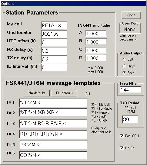
Besides the already mentioned (basic) parameters there are some more advanced ones. TX delay is being used to set the time delay between the PTT switching and the generating of audio (sequencing). RX delay is used to delay audio during switching so relay plops etc will not reach the decoder. The values are dependent on the switching time needed for your radio, amplifier and preamplifier. My values are set at (the default) 0.2 (seconds) – better safe than sorry. Like mentioned before: When audio appears it is immediately and constantly at 100% modulation. If your relays are still moving when this happens it can be very bad for various parts of your system.
The value for T/R period remains set at 30 seconds, the duration of a standard region 1 FSK441 period.
The final parameters which needs t be mentioned are the A, B, C, D parameters, used to adjust the audio level of the individual tones. I will get back to those later.
Close the screen by clicking Done.
Next we will set the switching of
the PTT (if PTT is done by the computer). On the WSJT MENU click on Setup after
which you will see the following:

First click on Set COM port. Now you must enter the number of the COM (serial) port to which your PTT is hooked up. Usually this will be 1. There are some rumors that COM ports on expansioncards don’t always function properly. I don’t know of any details and solutions to this are outside the scope of this article.
After setting the COM port it is smart to also click on DTR. Most radio interfaces use either DTR or RTS but there is usually no harm in allowing both. Check the instructions which came with your interface. The non-switching (or hanging) of the transmitter is often the result of this setting. Try other combinations as needed. The hanging of the transmitter (not dropping the PTT) seems to happen on occasion when using a COM-port expansioncard. As mentioned earlier if you want to use the parallel port for switching try PTT32 http://rudius.net/oz2m/software.htm and see if that works. I have not tested this software so can not give any comments on this.
Finally we must set some options:
On the MENU select Decoded, then
FSK441, then
![]()
Shorthand messages are not used in Region-1 and setting this parameter prevent many birdies or rattles from incorrectly decoding.
For future use you should also put checks on MENU -> Decoded -> JT65 -> Fast CPU (if your PC is above 1GHz in speed) and No Shorthands on Tx1. Both settings are used in JT65 which is not further described in this paper but if you have about 50W output and a 10dB antenna you can also make EME QSO’s.
First operational tests
The image of the main screen a little further down in the text goes with this description.
We start with the radio switched off.
If the current mode in the program (see the yellow mode indication) is not FSK441A then select FSK441A from the MENU->MODE.
Press button <A> (right-hand bottom side below Tune). If all works well the interface will now switch to transmit. If not, check if the switch settings are correct. If switching does take place then press the large <TX Stop> button on the right.
After proper completion of this test, switch on your radio at the lowest possible output level, mode USB, switch AGC OFF or FAST if no OFF available. Press button <A> again. Now the radio should switch into transmit mode. IF this works, then press <TX stop> again. If the radio does not switch to transmit, check the PTT connections.
We will now set the receive side. Press the RECORD button (left), wait about 5, 6 seconds then press STOP. A green line should show in the display left hand side. Depending on the noise on the receiving frequency this line will be more or less flat. In the status bar at the bottom should be a text: “RX noise: xxx”. This value should be around 0. Some 2dB more or less is not critical. You can experiment for optimum settings in your configuration later. In my situation -3dB appears to be working quite nicely, but this is very likely radio and interface dependent. Set this value via MENU->SETUP‑>Adjust RX volume control. Some more advanced cards like the M-Audio Delta-44 do not allow changing the volume in this manner. For those you should consult the documentation on how to set the proper levels. Of course the proper level can also be set by adjusting the audio out levels (AF & RF gain) on the receiver if you do not use a line level output.
The buttons A, B, C, D are intended to generate each one of the FSK441 tones for test purposes and send them via the soundcard to the radio. Check the radio output while pressing each tone individually. Each tone should deliver the same output. A difference of up to 10-20% is acceptable even though the closer together the output is, the better the signal can be decoded… If there is too much difference the level of the strongest tone(s) should be decreased in the Options screen. The values can vary between 0-1. For the proper procedure see the WSJT manual version 3, page 8.
Parameter settings.
To Radio = the callsign of the station heard or to be worked. This is also the first part of the filename of saved audiofiles.
Grid = The locator of the station in To Radio. Usually the locator can be retrieved from the WSJT database via the <Lookup> button. There are some good databases to get started with such as the WSJT-meteorscatterdatabase from DL8EBW http://www.mmmonvhf.de/ This database should be put in the WSJT directory after unzipping. If locators are not available in the database or if you suspect/know that they are incorrect they can be retrieved on-line from the ON4KST database at http://www.on4kst.com/chat/start.php by using the /SHLOC callsign command.
Add = Add or update a callsign and locator to the WSJT database to have this data available automatically in the future.
Any 6 position locator in the GRID field will result in automatic calculation of the distance (QRB) and direction (QTF) to this locator. If the full locator is not available try to enter something which is close. If the last 2 positions are not known I usually enter kk (approximately the middle of the square) to force a calculation. For normal use this will be close enough. In the example the calculated QTF is 157 degrees. There are two additional fields, the red “Hot A:” and normal “Hot B:”. These are the theoretical best directions to have common reflections towards the entered locator. Theoretically the red direction (“Red hot”) should be best, however in my experience with a3wl yagi beaming direct usually works best. The beamwidth is often more than the calculated offset. In this particular situation a QTF of about 160 degrees was used, somewhere in between. By the way, when using stacked longboom yagi’s the situation may well be different.
Decodingparameters are grouped in the center of the screen. For most parameters the optimum value will be different per operator or station used. The default values are a good start. If you play to much and need to get them back press the <Defaults> button.
W=minimum duration of a burst before attempting a decode. Default value 40ms and most usable. This durating allows decode of a sensible number of characters, a shorter value would cause many false decodes. In a very quiet environment is maybe be possible to use W=20.
Sh=Shorthand Messages. These are not used in Region-1 and should be switched off by setting the value to +99. The No Shorthands setting (earlier) makes sure that after a restart of the program this value will again be +99.
Tol=Tolerance or bandpass filter width. This parameter should be used in combination with the RIT control on the radio and the DF value of the decoded bursts. Will be discussed later.
QRN=A value which indicates QRN sensitivity. In a very quiet environment this can be set to a lower value. For me it is usually the default value of 5.
Zap=Birdiezapper. If there are unwanted birdies, whistles or similar signals in the passband – usually recognized by yellow lines or bands in the spectrumdisplay – check this field to notch them. This will often improve decoding under those circumstances.
Sh msg=TX shorthand messages. Never check this box, shorthand messages are not used in Region-1.
Report=Report to be send to the other station according to the MS procedure. Will be discussed later.
Custom=By clicking on this button a second message screen will show which can be used for alternate (fixed) messages which do not comply with the MS procedure. I have never had use for these.
TX First=This parameter determines the transmit period. When checked you will transmit in the first period (normally seconds 00-30), when unchecked transmit will be second period (seconds 30-00). Set this parameter based on the MS procedure or per local agreement.

Operational items
In the top left graphics box a 30 second period is shown. The GREEN line shows the received signal. Below the green line you can see a small vertical RED line. This red line is the location (time) where the program found the strongest signal during this period. In this example the red line is at 16.9 seconds in the period where the program started the automatic decode. The value in the little green square below the timeline shows the last cursor location in the box (21.4 seconds). This is very convenient if you hear bursts which the program does not automatically decode. Move the cursor to the time of the burst and click at that location. In this case also try RIGHT mouseclick, RIGHT mouseclick uses a different decoding algorithm with often surprisingly good results. For me personally RIGHT mouseclick is a very valuable feature.
The graph at the top right of the screen shows a representation of the received signal. The PURPLE line indicates the basic audio signal, the RED line shows the tones in the (lastly) decoded burst. In this example you can see tone B a little bit stronger than the other 3 tones but all 4 individual tones are recognizable.
In the grey part below the spectrumfields are the filename for this period: IW9FRA_050118_145100, being: To Radio callsign, the date and the time of this period.
Additionally the column headings for the decoded text box:
FileID=Time of the receive period
T= Seconds within the period where decoding started
Width=Duration of the burst in
milliseconds
dB=Maximum strength of the decoded signal in dB’s over the preceding noise
S/N=Signal to noise ratio
DF=Delta frequency of Difference in Frequency. This value shows the number of Hz which the received signal is above (positive number) or below (negative number) the receiver frequency. This value is not always reliable. There can for example be Dopplershift on received signals. I have noticed that the latest versions of WSJT appear to have problems determining a correct value for DF even on a stable signal. I personally use WSJT version 4.3.4 to get the proper value.
Finally the buttons which have not been mentioned:
Gen Std Msgs=After entering the callsign of the other station in the To Radio field and a report in the Report field, a press on this button will generate properly formatted messages. Warning: Pressing this button will reset the currently selected transmit message to message 1. Not paying attention to this “feature” may result in a failed QSO (I speak from experience).
Auto is On=Pressing this button will start the automatic RX/TX cycle according to values set. The selected message is being transmitted during the TX period until another message is being selected or the button is pressed again to stop the cycle. To immediately stop transmitting press the TX Stop button.
Record=Receive a full period and decode afterwards. This period start immediate when the button is pressed and stops after a full periodlength.
Monitor=Receives and decodes both (first and second) periods until the STOP button is pressed.
Play=Playback (audio) the last available period.
Stop=Opposite of start.
Save Last=Create a WAV file of the last available period in the RXwav folder (below the WSJT program folder). Warning: Regular saving in the RXwav folder can result in a full harddisk. Preventing this is important, cleanup the RXwav folder on a regular basis or save the files in a different location.
Decode=Decode the received period again for example after changing some of the decode parameters.
Erase=Clear the text screen.
TX1-TX6=Pressing 1 of these buttons will switch PTT and start TXing the selected message. Use these buttons only during transmit when you want to switch to a different message, for example as the result of newly received information. In other case select the message to transmit next by selecting the bullet in front of the button.
TX Stop= Stops transmitting immediately. The automatic RX/TX cycle will continue, to stop that press the Auto is On button.
The making of a QSO
After discussion the necessary settings and parameters it is now time for the first QSO. This will be discussed in part 2 of this paper. If you can not wait until then, take a look in the 144MHz chat of ON4KST at http://www.on4kst.com/chat/. You will surely find someone who will try to help you get started.
For the latest news about DXpeditions see the MMMonVHF pages: (http://www.mmmonvhf.de/
73
Catharinus PE1AHX
![]()
![]()
See
http://www.pe2pe.eu for all WSJT info and manuals in many languages